If you’ve ever been stuck with a wonky current transformer (CT) throwing off your power measurements, you know how frustrating it can be. I’ve been selling CTs for over 8 years now, and let me tell you—half the issues folks reach out about aren’t even the CT itself, just a little troubleshooting misstep. Today, I’m walking you through the real, no-fluff way to troubleshoot a CT, straight from a supplier who’s seen it all. No corporate jargon, no "industry-standard" fluff that sounds good but doesn’t work. Just actual fixes I’ve helped customers nail down. Current Transformer
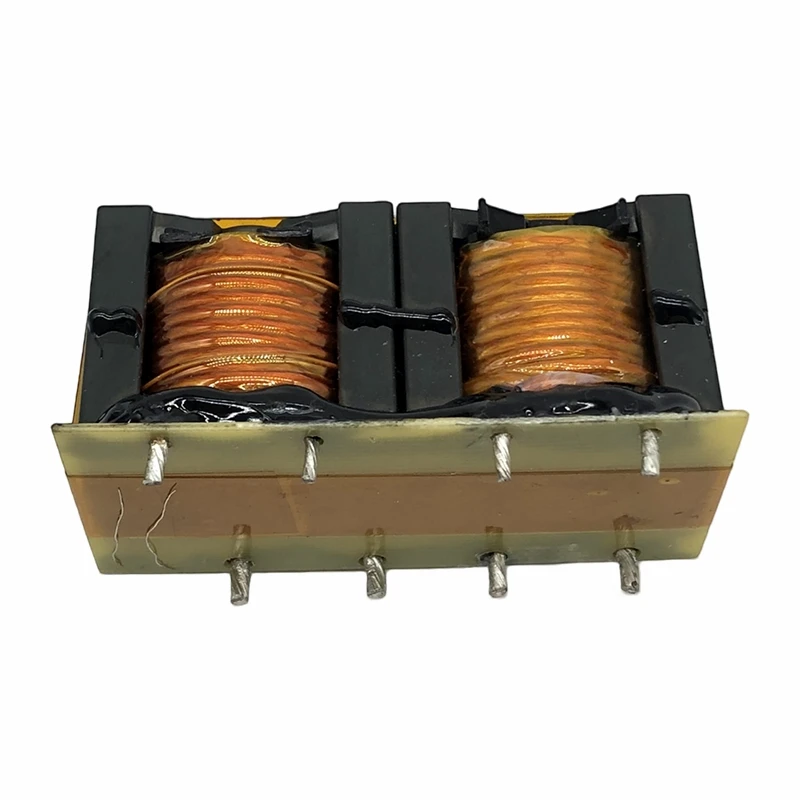
First off, let’s get one thing straight: CTs are simple, but they’re sensitive. They take high current and step it down to a safe level (usually 5A or 1A) for meters, relays, or monitoring gear. Mess up even one small step, and you’re getting bad data—or worse, a safety hazard. I always tell new customers: before you even grab a multimeter, write down what the issue actually is. "My meter reads 2A instead of 5A" is way easier to fix than "it’s broken." Jot down when it started—after a power outage? After a new piece of equipment was installed? That little detail alone cuts troubleshooting time in half. My go-to first question when someone emails: "What’s the exact symptom, and what changed lately?" 9 times out of 10, they say something like "We added a 100HP motor last week, and our generator read 0 instead of 120A." Bam—already narrowed down.
Now, let’s start with the easiest, most common issues, because 70% of CT problems are super simple. First, check the wiring. I can’t tell you how many times someone’s tightened a wire so loose it’s not making contact, or mixed up the primary and secondary leads. Wait—primary is the big wire going through the CT window, right? Secondary is the two smaller leads that go to your meter/relay. Let’s break this down step by step.
First, make sure the primary conductor is actually going through the CT window. This sounds stupid, but I’ve seen it. A tech ran the power line next to the CT, not through it, and wondered why the reading was zero. If you have a bar-type CT, check that the bar is fully inserted, not just half-way. Also, check for any splits in the window—if you closed the CT around a cable and didn’t click it all the way shut, that’s a gap, and you’ll get garbage readings. I always tell my team to remind customers: give the CT a little tug on the window to make sure it’s latched. If it feels loose, that’s a problem.
Next, the secondary wiring. This is where I see the most mistakes. First, never, ever leave the secondary leads open. CTs are current devices—if you leave the secondary open, it builds up insane voltage (like thousands of volts) that can kill you or destroy your gear. If you have an open CT, shut off power first—don’t mess with it live. Now, check the secondary connections: are they tight? Are they corroded? I had a customer last month who had a green crust on his secondary terminals from condensation in a panel. That corrosion was adding resistance, so his reading was 15% lower than it should be. Grab a screwdriver, loosen the terminals, clean them with some sandpaper (light, don’t ruin the metal), and tighten them back down. Also, check if you mixed up the polarity. Secondary leads have markings—usually S1 and S2. If you swap S1 and S2, your meter will show negative current, which can throw off load calculations. That’s an easy fix: swap them back, or flip the secondary leads around. One quick tip I share: take a quick photo of the wiring before you touch anything. That way, if you mess up, you can just put it back how it was.
Okay, wiring checks done. If that didn’t fix it, move on to the next step: test the CT with a multimeter. Wait—can you test a CT with a regular multimeter? Yes, but not the way you’d test a resistor. CTs are AC devices, so a DC multimeter won’t work. You need an AC current clamp meter (funny enough, a clamp meter is basically a CT itself) or an AC voltage setting. Let’s start with the secondary side, because that’s safe. First, make sure the secondary is shorted (not open—remember that safety thing). Now, if you can, pass a known current through the primary. For example, if your CT is rated for 100A primary to 5A secondary, you can use a variable load (like a small motor or a heater) to put 50A through the primary. Then, measure the secondary voltage with your multimeter AC setting. You should get roughly half the rated voltage (for 100A: 50 primary = ~2.5 secondary). If you get zero, the secondary is open inside the CT—meaning the winding broke. If you get way too high or way too low, the CT might be faulty. Wait, but before you jump to that, check the ratio. Oh right—CTs have a ratio printed on them, like 200:5, meaning 200A primary = 5A secondary. If you’re putting 100A through, you should get 2.5A secondary. If your reading is way off, it could be a ratio mismatch—like someone installed a 200:5 CT for a circuit that actually needs 400:5. That’s not a CT fault, that’s a wrong CT size. I see this all the time when people guess CT size instead of calculating it correctly. Pro tip: when sizing a CT, calculate your maximum load current, then pick a CT where your max current is 70-80% of the primary rating. So if your max current is 150A, a 200:5 is perfect—you don’t want to run at 100% capacity all the time, that causes errors.
Another common issue: core saturation. CTs have a saturation point, where too much current flows through the primary, and the core can’t handle it anymore. That means the secondary current stops increasing linearly, so your readings are way off. When does saturation happen? Usually during motor start-up—motors pull 5-6 times their rated current when starting. If your CT is rated for continuous 200A, but your motor starts at 1000A, that CT will saturate during start-up, and your meter will show a lower current. How do you check for saturation? Watch the reading during start-up. If it’s way lower than expected when the motor is starting, then back to normal once it’s running, that’s saturation. The fix here is a CT with a higher primary rating—get one that can handle the peak start current, or use a low-output CT (like 1A instead of 5A) which has a higher saturation voltage. I always advise customers to tell me their start-up current when ordering, not just their running current—That way I can pick the right CT for their application.
Wait, what about if you have a digital meter and it’s showing "no input" or a weird error? Don’t just blame the CT. Check the burden of the secondary circuit. Burden is the total resistance in the secondary wiring plus the meter’s internal resistance. Each CT has a maximum burden rating, like 10VA. If your total burden is higher than that, the CT can’t push enough current to the meter, so you get bad readings. How do you calculate burden? It’s easy: add up the resistance of each secondary wire (usually around 0.1 ohm per 100ft, so 200ft of wire is 0.2 ohm) plus the meter’s burden (usually printed on the meter specs, like 0.1 ohm). Multiply total resistance by the square of the secondary current (I²R) to get VA. If that number is higher than the CT’s max burden, you need either shorter wires, a meter with lower burden, or a CT with a higher burden rating. I had a customer a while back who had 300ft of secondary wire to a meter in a remote substation. His burden was 12VA, but his CT was only rated for 8VA—so he kept getting reading errors. We swapped the CT for one with 15VA burden, and it fixed it immediately. No need to run new wire, which saved him thousands. That’s the kind of thing only a supplier who’s been there catches—most techs don’t think about burden until it’s an issue.
Now, let’s talk about more severe issues, like physical damage. Did the CT get hit? Did a storm cause a power surge? Did someone over-tighten the primary conductor, which can bend the core? If the CT is cracked, or the window is bent, that’s a sign it’s damaged. Even a tiny crack in the core can throw off accuracy by 5% or more. How to check for physical damage: do a visual inspection first—no need for fancy gear. Then, if you can, do a ratio test like I mentioned earlier. If the ratio is way off from what’s printed, that’s a good sign the core is damaged or the winding is shorted. Wait—winding shorts are another big one. If part of the secondary winding is shorted, the output current will be lower than expected. How to spot that? If you do the primary current test, and the secondary current is way lower than the ratio, that’s a shorted winding. CTs with shorted windings usually don’t show external damage, so you have to test them. My team always keeps a spare multi-meter and current clamp on hand when we visit customers for this exact reason—way faster than renting gear.
Safety is non-negotiable here. I can’t stress this enough: CTs are live with high voltage on the secondary if open, and high voltage on the primary when the circuit is energized. Never work on a CT without turning off the primary power first, unless you’re using a clamp meter (which is safe to use live, since you’re not making direct contact). If you have to test a live primary current, use a quality clamp meter, and make sure your hands are insulated. I’ve seen too many techs get zapped because they forgot to short a secondary before working on it. That’s why every CT I sell comes with a quick safety sheet taped to the box—no excuses.
Wait, let’s go through a real example to make this concrete. Last month, a customer texted me in a panic: their 400:5 CT showed 0A on their generator, even though the generator was running at full load. Here’s what we did step by step: 1) Jotted the symptom: reading 0, generator running. Changed: generator was installed last week. 2) Checked primary: generator cable ran through the CT window? Yes, but the CT window wasn’t latched. We clicked it shut, reading went up to 1A (way low, but not zero). 3) Checked secondary connections: the S1 lead was loose. Tightened it, reading went to 2.4A—perfect, that’s half of 5A, since we were running 192A (close to the 200A load on the generator). Turned out the installer was in a hurry, didn’t latch the CT or tighten the secondary. That’s the stuff that gets missed when you’re rushing a job.
If you’ve gone through all these steps and still have an issue, what next? It’s probably a faulty CT. But before you toss it, check if it’s under warranty. All the CTs I sell come with a 5-year warranty, so if it’s within that time, we’ll replace it for free, no questions asked. Wait—don’t try to repair it yourself. CT cores are precision-wound, and opening them ruins the accuracy. I’ve had customers try to fix a broken secondary lead by soldering it, only to get a ratio error that’s worse than the original problem. It’s not worth it—send it back, we’ll test it in our shop, send a replacement, and take the old one off your hands.
At the end of the day, troubleshooting a CT isn’t rocket science. It’s about being methodical, starting with the simplest stuff, and not skipping safety steps. I always tell my customers: don’t assume the worst first. 9 times out of 10, it’s a loose wire, a window that’s not latched, or a wrong CT size. If you’re stuck, don’t guess—reach out. We’re not just a supplier who boxes up parts and ships them; we help with troubleshooting, size calculations, and anything else you need. We know CTs inside and out, because that’s all we do. Whether you’re a small shop with one generator or a big utility with a dozen substations, we’ve got the right CT for you, and the help to make it work.
If you’re dealing with a CT issue right now, or you need to replace an old, faulty one, hit us up. No pressure, no salesy pitch—just tell us what you need, and we’ll make it easy. Stop fighting with bad measurements, we’re here to get your power systems back on track.
High-voltage Transformer References
- Electrical Installation Work, 7th Edition, Trevor Linsley
- Current Transformer Application Guide, American National Standards Institute (ANSI)
- Power Systems Measurements: Theory and Practice, S. A. Swarup
- NEC Handbook 2020, National Fire Protection Association (NFPA)
Dongguan Hensiron Electric Co., Ltd.
As one of the most professional current transformer suppliers in China, we have world-leading production equipment and strong manufacturing capabilities. Please feel free to buy high quality current transformer made in China here from our factory. Customized orders are welcome.
Address: Building 4, Xinxing Industrial Zone, Wangao Road, Wanjiang Street, Dongguan City, China
E-mail: jessica@dghensiron.com
WebSite: https://www.dghensiron.com/
